The Stardust NAVCAM data calibration procedure takes the EDR (raw) Data Number (DN) images and converts them to radiance (or just to data calibrated DN if the exposure duration is zero).
The procedure comprises several steps summarised in the table below. The procedure uses information from the EDR image label as well as from ancillary sources such as calibration files and model parameters.
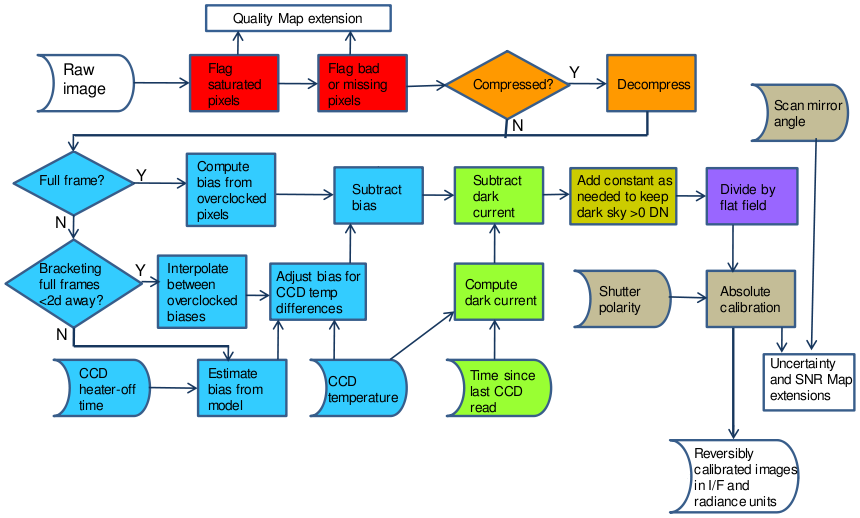
See also Figure 1 below.
The procedure also appends quality, signal-to-noise and uncertainty maps as PDS OBJECTS to the data-calibrated output image in the output file.
Refer to [KLAASENETALL2011B] for details.
| Step Mnemonic | Description | Calibration info or file(s) (see data set directory CALIB/) | Uncertainty |
|---|---|---|---|
| MASK |
Flag any pixels that were outside WINDOWs and/or
bad and/or missing. The flags are stored as bits
in the QULMAP_IMAGE OBJECT. Flagged pixels are not
processed any further in the data calibration
process.
| NCBADP.LBL - list of bad pixels | - |
| SATU | Flag saturated pixels based on raw Data Number (DN) value (255 if compressed; 4095 if uncompressed). Also flag pixels that are above or to the right of the saturated pixels as potentially pixels into which excess signal has bled. The flags are stored as bits in the QUALITY_MAP OBJECT. | - | - |
| DCMP | For uncompressed images do nothing. For compressed images, invert on-board 12- to 8-bit NAVCAM compression lookup table: replace 8-bit DN with center of corresponding 12-bit bin from lookup table. Save the bin size for each pixel for NOISe step (below). | COMPTABL.LBL - compression lookup table in NAVCAM ROM | - |
| BIAS |
Calculate bias and subtract from DNs.
Use the first of the following methods which succeeds.
|
|
|
| NOIS | Calculate sum-squared NOISe from BIAS-subtracted DNs. Noise will be divided into BIAS- and DARK-subtracted DNs to make Signal-to-Noise Ratio (SNR) map, SNRMAP_IMAGE OBJECT. NOISe units are DN-squared. |
| - |
| DARK | Calculate dark current for and subtract from current image DNs. Dark current builds up continuously from end of previous CCD read and through EXPOSURE_DURATION of current image. Get time (MET) of previous NAVCAM read event from table of NAVCAM events. Dark current rate model is K * tλ, DN/s; t is time since previous read in seconds. |
| Twice the dark model estimate. |
| BDFX | Bias- and Dark-Fix. Examine median of result of previous step to see if median is less than zero. If it is, add some DN back to the image to make that median zero. When calculating this median, exclude the N brightest pixels where the area of N pixels is equivalent to a circle of a given radius at the range of the comet. N will be zero for all but the encounter flyby images. | Nominal radius to use: 3.5km (9P/Tempel 1); is big enought to include some coma. | - |
| SNRM | Calculate SNR Map for SNRMAP_IMAGE OBJECT. Divide DNs from BDFX step by result of NOISe step. | - | - |
| FLAT | Divide by flat-field image to remove pixel-to-pixel variation. | NAVCAMNORMPRLSLOPE_TESTSL1.LBL - flat-field file | - |
| RATE | Divide DN from output of FLAT step by per-pixel exposure duration to get DN rate, DN/ms. This step is not performed if current image is a bias frame i.e. if the nominal exposure time is zero. Nominal exposure duration is in keyword EXPOSURE_DURATION, in ms, to which a per-pixel offset is added to get the actual exposure duration for each pixel. The per-pixel exposure offset, in ms, is a polynomial function of image line number, L, and shutter blade polarity: forward=FWD; backward=BCK; unknown=UNK. Shutter blade polarity is set to FWD at NAVCAM power-on, and toggles between FWD and BCK for every non-bias frame. See NAVCAM_SHUTTER_POLARITY.LBL for more details. |
| 0.1ms in pixel exposure duration |
| ABSC | Convert from the DN rate (DN/ms) output of the previous step to radiance. Also save the I/F coefficient. |
| If the scan mirror angle is less than 17deg, then 100%, else zero. |