
STARDUST camera information provided by George Fraschetti, Mark Schwochert and Tom Radey, JPL
The Navigation Camera (NC), an engineering subsystem, will be used to optically navigate
the spacecraft upon approach to the comet. This will allow the
spacecraft to achieve the proper flyby distance, near enough to
the nucleus, to assure adequate dust collection. The camera will
also serve as an imaging camera to collect science data. The
data will include high-resolution color images of the comet nucleus,
on approach and on departure, and broadband images at various
phase angles while nearby. These images will be used to construct
a 3-D map of the nucleus in order to better understand its origin,
morphology, and mechanisms, to search for mineralogical inhomogeneities
on the nucleus, and potentially to supply information on the nucleus
rotation state. The camera will provide images, taken through
different filters, that will give information on the gas and dust
coma during approach and departure phases of the mission. These
images will provide information on gas composition, gas and dust
dynamics, and jet phenomena, if they exist.
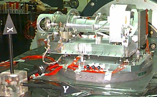
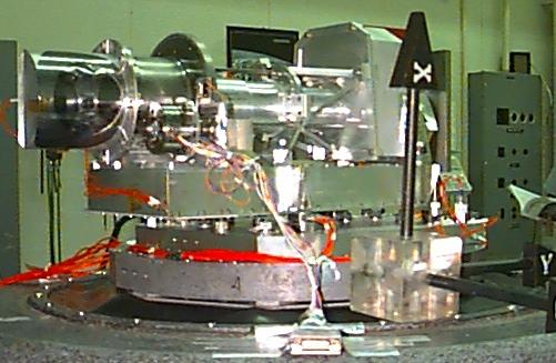
In order to meet these science and optical navigation objectives
the NC design was developed utilizing a Voyager Wide Angle Optical
Assembly. Additionally; the NC has a newly developed scan mirror
mechanism to vary the camera viewing angle and a periscope to
protect the scanning mirror while the spacecraft flies through
the comet coma. The NC is a framing charge coupled device (CCD)
imager with a focal length of 200 mm. The NC has a focal plane
shutter and filter changing mechanism of the Voyager/Galileo type.
The detector is a charge coupled device (CCD), cooled to suppress
dark current and shielded from protons and electrons. The electronics
contain the signal chain and CCD drivers (located in the sensor
head), command and control logic, power supplies, mechanism drivers,
a digital data compressor and two UARTs too interface with the
spacecraft Command and Data Handling (C&DH). NC command and
telemetry functions will also be handled by the electronics including
storage of science commands, collection of science imaging data
and telemetry, transmission of imaging data and telemetry to C&DH
and receipt of commands from C&DH. The NC uses a data rate
of 300 kpixels for transferring data to the C&DH. There are
also the option for data reduction with 12 bit to 8 bit square
root compression, windowing and error free compression within
windows.
The NC consists of the following major functional elements.
(a) Optics
(b) Filter Wheel and Shutter Mechanisms
(c) Detector
(d) Scan Mirror Mechanism
(e) Periscope
(f) Electronics and NC Control
The optics subassembly is inherited hardware designed, build and tested for the Voyager Project. It is a Petzval-type refractor lens with a 200 mm focal length, f/3.5 and a spectral range 380 nm - 1000 nm. A schematic diagram of the optical design is presented in Figure TBD and the optical characteristics listed in Table 1. The optical components, with the exception of the filters, are manufactured from LF5G15 and BK7G14 materials which are radiation resistant. A new field flattener element, located in front of the CCD window, was designed for Stardust to reduce field curvature and to provide additional CCD radiation shielding. The optics are supported on three invar rods that athermalize the system to keep the camera in focus over the operating temperature range. The optical barrel assembly mounts to the filter wheel and shutter assembly utilizing an aluminum truss structure. The housing and truss are also inherited hardware from Voyager. There is a small incandescent lamp, spider mounted in front of the first lens element, that can be used for in-flight calibrations.
Because radiation resistant optical materials were used to harden
the optics, the lens has a poor broad band MTF performance (axial
color). The theoretical MTF for the spectral range 380 nm to
1100 nm is 30% at 32 lp/mm. The thickness of individual filters
will be optimized to improve the MTF over the filters passband.
| Table 1 - Optics Characteristics |
|---|
| Focal Length | 200mm |
| Relative Aperture | f/3.5 |
| Spectral Range | 380 - 1100 nm |
| Resolution | 60 microradian/pixel |
| Field of View | 3.5 x 3.5 degrees |
The NC filter wheel assembly is inherited Flight Spare hardware from the Voyager Project. The assembly contains an eight position filter wheel and a driving mechanism as can be seen in Figure 3. To actuate the mechanism a pulse is sent that energizes the linear solenoid, thereby rotating the rocker arm by means of the connector rod. The pawl, pivoted on the rocker arm, is driven toward the next wheel cog. At this point the pawl releases latch A from the cog wheel, extends the drive spring and then engages the next cog on the wheel. This puts the mechanism in the cocked position. When the solenoid is de-energized, the rocker arm and pawl are returned to there original position by the drive spring, which advances the filter wheel one position. During this travel the A latch follows the pawl inward and is in position to stop the filter wheel at the end of the stroke. The back latch B ratchets over the cogs, preventing the wheel from back lashing. A series of photo-diodes are uncovered by a pattern of small apertures in the filter wheel which are unique for each filter position. Thus the filter that is in the optical path is known for each image taken and is included as part of the engineering telemetry.
The spectral response of the camera is controlled by bandpass
filters. The bandpass filters for Stardust will be new and will
be installed into the filter wheel to replace the Voyager filters.
In Table 2, the filters are identified along with some of their
characteristics and their position location (TBD) in the filter
wheel.
The NC shutter assembly is also inherited Flight Spare hardware
from the Voyager Project. As shown in Figure 4, the
device is a two-blade focal plane mechanism. Each blade is actuated
by its own permanent rotary solenoid. The duration of the exposure
is controlled by the time interval between two pulses (an open
pulse and a close pulse). The open pulse powers the "leading"
blade and the close pulse powers the "trailing" blade.
The exposure sequence starts with the leading blade covering
the aperture. An open pulse moves the leading blade, uncovering
the aperture, and the close pulse moves the trailing blade, in
the same direction, covering the aperture again. The permanent
magnets in the rotary solenoid of each blade hold the blades in
a detent position when the shutter is not powered. Exposures
can be taken with the blades moving in either direction. A total
of 4096 exposure times are available that range from 5 ms to 20
s, in 5 ms increments. There is also a bulb command, for longer
exposures, that allows the shutter to be held open for any desired
length of time.
The NC uses a charge coupled device (CCD) detector packaged for
the Cassini Imaging Science Subsystem (ISS). The operating temperature
range is -55oC to -25oC. The CCD has the performance characteristics
outlined in Table. The CCD is mounted in a hermetically sealed
package which is back-filled with argon. An operating temperature
of around -35oC is needed for suppression of dark current and
to minimize proton gamma and neutron radiation effects. The NC
employs passive radiative cooling to maintain the detector operating
temperature.
| Table 2 - STARDUST Filter Characteristics (updated 2000-03-17) |
|---|
| Optical Navigation | |||||
| NH2 Emission |
|
||||
| Oxygen (0[1D]) Emission | |||||
| C2 (C2 delta v=0 band) |
|
||||
| Yellow Continuum | |||||
| Red Continuum |
|
||||
| NIR Continuum |
|
||||
| HiRes |
|
Notes: All wavelengths are in nanometers. All filters have no requirements
for lambda <3000 or >11000.
| Table 3 - Sensor Characteristics |
|---|
| Format | 1024 x 1024 pixels |
| Pixel Size | 12 x 12 micrometers |
| Full Well | > 100,000 e- |
| Dark Current | < 0.1 e-/pixel/sec at operating temperature |
| Charge Transfer Efficiency | 0.99996 at operating temperature |
| Read Noise | < 15 e- rms |
This mechanism enables the stationary wide angle optics (flying
sidewise during encounter) to keep the comet in view during flyby.
The scanning mirror, located some distance forward of the camera
lens faces 45 away from the camera viewing axis. Rotating the
mirror about the camera axis at the proper rate enables comet
tracking during flyby. The mechanism is a single DOF device. It
requires proper spacecraft orientation so that the comet can be
viewed in a viewing plane originating at the scan mirror and oriented
perpendicular to the camera axis. The initial forward looking
view (0 position) is through a periscope which protects the scan
mirror. The mirror's home position is at -20where the camera sees
a black object on the spacecraft. Total mirror rotation is 220,
allowing views up to 20 beyond looking straight back. The maximum
rotational rate is approximately 3.1/sec.
The mechanism consists of a cylindrical section with mirror and
an anti backlash mechanism, the drive unit with motor, gearbox
and slip clutch and a base which houses the control electronics.
The cylindrical section is coaxial with the camera lens. It consists
of the rotational housing containing the mirror and a stationary
housing with an anti backlash mechanism attached to it. The sections
of the housing which hold the main bearings are made from titanium
to enable accurate operations over a 100C temperature range. A
smooth rotational motion is further assured by a duplex bearing
pair, by precision gears and an anti backlash mechanism utilizing
a negator spring to produce a constant torque against the rotational
motion. This should suppress pixel smear to approximately 2 pixels.
The mirror, made of zerodur, is bonded to flexures which attach
to the rotational housing. Baffling rings along the optical path
assure that stray light is being reflected away from the lens.
The drive unit next to the housing consists of the following components:
A brushless DC motor from American Electronics Inc.: Vmax=36V,
T=10oz-in, n~1200rpm. This motor was previously space qualified
for the MISR project. The motor is flanged onto the four stage
planetary gearbox made by American Technology Consortium: e=252.6:1,
=55%. The gearbox was previously space qualified for the Mars
Pathfinder project. A slip clutch at the gearbox output shaft
utilizes a set of Belleville springs to keep the pinion's transmitted
torque within a predetermined limit. It prevents mechanical damage
in the event of control failures which might cause the mechanism
to over-rotate and hit the stops that limit travel. The pinion
is engaged with the main gear on the rotational part, providing
a fifth transmission stage. The overall gear ratio is 2518.6:1.
The periscope is an optical assembly that allows the scan mirror to look over the protective whipple shield while it is pointed forward, in a direction parallel to the space craft +X axis. This is to protect the scan mirror from particle impingement, that would significantly degrade it's performance, during cruise, upon approach and while flying through the comet coma. The periscope contains two rectangular mirrors mounted at 45 with respect to the space craft +X axis.
The mirrors are made out of aluminum to reduce the rate and amount of degradation from particle impacting. For light weighting, the mirrors are fabricated using an aluminum foam core composite material with solid face sheets braised onto the front and back surfaces. Single point diamond turning will be used to figure the reflective surface of the mirrors. Since the forward looking mirror is exposed to the impacting particles it will be post polished and receive only a very thin protected aluminum coating. While the mirror facing away from the particle stream will be nickel coated and post polished with a thin protected aluminum coating. This process achieves a much better mirror figure and smother surface finish but tends to flake off when exposed to particle impact.
The periscope structure will be a graphite/epoxy
composite construction. This material was chosen to make the
structure light and to reduce thermally induced distortions from
the spacecraft to the periscope assembly. Each mirror will be
kinematically mounted to the composite structure using three triangular
bipod flexures. The periscope is only utilized when the scan
mirror is looking forward. After the scan mirror has rotated
approximately 15-20 down toward the spacecraft -Z axis it no longer
imaging through the periscope. The periscope was designed so
that the images taken while the mirror was partly looking through
periscope could still be used for optical navigation.
The electronics for the NC consists of two major parts the camera electronics and the scan mirror electronics. The sensor head electronics ( part of the camera electronics) is mounted a chassis that is located behind the focal plane of the optics while the rest of the camera electronics and the scan mirror electronics are housed in the baseplate support. The NC electronics control NC functions and process NC commands and telemetry. The NC electronics is powered from the space craft 28 volt regulated and 34 volt unregulated supplies.
The portion of the camera electronics mounted behind the camera is called the sensor head electronics. These electronics support the operation of the CCD detector and the preprocessing of the detector data. The pixel data is quantized to 12 bits giving an intra-frame dynamic range of 4096. Detector readout rate is fixed at 300 kpixels / second. In addition, a direct access port is included in the sensor head electronics to send telemetry to the NC ground support equipment. This port is used for ground testing only.
The remainder of the camera electronics is called the main electronics.
The main electronics provides the power and performs all NC control
functions. This includes a CCD clock generator, image compressor,
image buffer, mechanism and lamp drivers, telemetry mux and converter,
bus controller, UARTs and power supplies. The spacecraft specified
RS-422 Bus is used for communication with the Command and Handling
(C&DH). A high speed bus is used for transmission of image
data and an low speed bus is used for sending and receiving commands
and telemetry.
The NC scan mirror mechanism has it's own interface with the
space craft. This includes a separate power interface, a bi-directional
low speed RS-422 bus for telemetry and commanding transmission,
a low speed RS-422 bus for outputting for motor rotation pulses,
a discrete output for motor direction. All interfaces with the
scan mirror mechanism are done through one 24 pin connector designated
J2 that is mounted in the NC baseplate.
NC Electronics provides one data rate of 300 kbpxls per second.
The pixel data from the NC can be processed within the NC in
several ways. The default processing is to transmit the converted
12 bit data. When the data compression is turned on the 12 bit
data is compressed to 8 bits using a square-root compression algorithm.
This is accomplished via a look-up table stored in ROM.
The camera electronics is required to draw less than 8 watts
and the scan mirror less than 10 watts steady state. Operational
constraints are placed on the NC to limit the power drawn by NC
from the spacecraft at any one time.
At power turn on, the NC registers are all set to zero. At this
point the camera is in an "idle mode" with all clocks
running, waiting to receive commands. The camera will remain
in this state until the first command is received. The state
of the mechanism will be what they were when the camera was last
turned off.
In response to a concern that the NC boresight may, in a spacecraft
fault condition, be exposed to the sun (accidentally incident
sunlight), a methodology to protect the shutter and focal plane
of the camera was developed. The NC safe state is defined as
placing a narrow band filter in the optical path and opening the
shutter. To reset the NC to a normal operating state a power
on reset will clear the FPGA lockup.